
Title
MAX7219 LED Matrix Driver

What It Is
The MAX7219 is a display driver chip made to control LED matrices or 7-segment displays without forcing the microcontroller to manage every LED directly.
What It Does In This Project
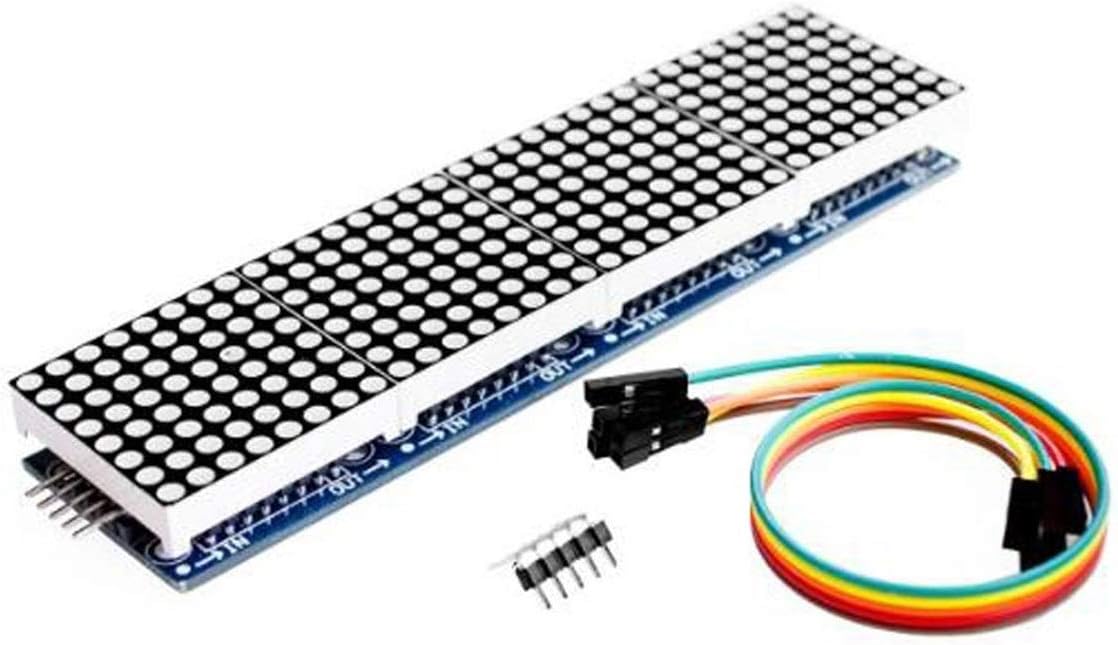
- drives the 8x32 LED matrix display
- refreshes the LEDs fast enough to look steady
- lets the MCU send display data in an organised way
Origins And Background
The MAX7219 was designed by Maxim Integrated. It became popular because it simplified LED driving. Without a driver chip like this, large LED displays would need many more MCU pins and more constant refresh work.
How It Communicates
- uses
SPI-style serial communication - the MCU sends data for rows, columns, and intensity
- multiple devices can be chained together for wider displays
Two Layers Of Pinout
There are really two different pinout ideas to understand here:
- the external module pins that connect the MAX7219 board to the MCU
- the internal chip connections that connect the MAX7219 to the LED matrix rows and columns
Students often mix these together at first, so it is worth naming both layers clearly.
Module Pinout
On the common MAX7219 matrix module the useful pins are usually:
VCC: powerGND: groundDIN: serial data inCSorLOAD: latch / chip selectCLK: serial clock
Some boards also expose matching output pins for chaining into the next display section.
MCU To Module Wiring
The Bluepill only has to talk to the driver board, not to every LED directly.
Course Wiring
In this course hardware:
DIN-> BluepillPA7(SPI1_MOSI)CLK-> BluepillPA5(SPI1_SCK)CS-> BluepillPA4VCC-> display supply railGND-> common ground
This is one of the clearest examples in the course of a microcontroller using a dedicated serial peripheral to push display data efficiently.
Driver To Matrix Connections
Inside the module, the MAX7219 connects to the LED matrix itself using:
DIG0toDIG7SEG AtoSEG GSEG DP
For a matrix, these are repurposed as row and column drive lines.
The exact row/column naming can look confusing because the chip was also designed for 7-segment displays. On matrix modules, the important idea is:
- one set of output lines selects one row at a time
- the other set of output lines decides which LEDs in that row light up
So the chip is not sending a separate wire for every LED. It is selecting rows and columns in a fast pattern.
How Multiplexing Works
The MAX7219 stores display data internally and then repeatedly scans through the matrix.
For one 8x8 section, the basic idea is:
- enable row 0
- drive the column pattern for row 0
- disable row 0
- enable row 1
- drive the column pattern for row 1
- continue through all 8 rows
- repeat continuously
That process is called multiplexing.
Persistence Of Vision
If the rows were scanned slowly, the display would flicker and we would notice the row-by-row update.
But the MAX7219 scans fast enough that human vision blends those updates together. This is the persistence of vision effect:
- each row is only lit for a fraction of the time
- the scan repeats quickly
- our eyes interpret the whole thing as one steady image
So even though the chip is really cycling through rows, we perceive a stable letter or pattern.
Why The Driver Chip Helps
Without a driver chip like this, the MCU would need to:
- manage row scanning itself
- manage column patterns itself
- refresh the matrix constantly
- handle current drive and timing details
With the MAX7219, the MCU can instead think at a higher level:
- send bytes for the display state
- let the driver handle the repetitive refresh work
That is a classic embedded design pattern: move repetitive hardware timing work into a dedicated peripheral or driver chip.
Why SPI Fits Well Here
SPI is fast and simple. It works well for pushing display data because the MCU can shift bits out quickly and the display driver can latch the result.
Physical Layer Notes
The communication uses clocked digital lines:
- data
- clock
- chip select/latch
That means the sender and receiver agree exactly when a bit should be read.
Why It Matters
This is a good example of an interface chip doing the repetitive low-level work so the MCU can think at a higher level like “show this bitmap” or “scroll this text”.
Teaching Focus
- SPI as a fast serial protocol
- why display drivers exist
- multiplexing and refresh
- why hardware offload is useful
Datasheet Navigation Tips
Look for:
- pinout
- serial timing diagrams
- register descriptions
- current and brightness settings
- cascade connection examples
Interesting Detail
Even though many LEDs appear to be on at once, the driver is really scanning the matrix a row at a time and relying on persistence of vision to make the image look steady.
Good Questions To Ask Students
- Why not connect every LED directly to the MCU?
- Why does a display driver help us?
- Why is SPI a good match for a display chip?
- Why can a row-scanned display still look like a solid image?
- What jobs is the MAX7219 doing so the MCU does not have to?